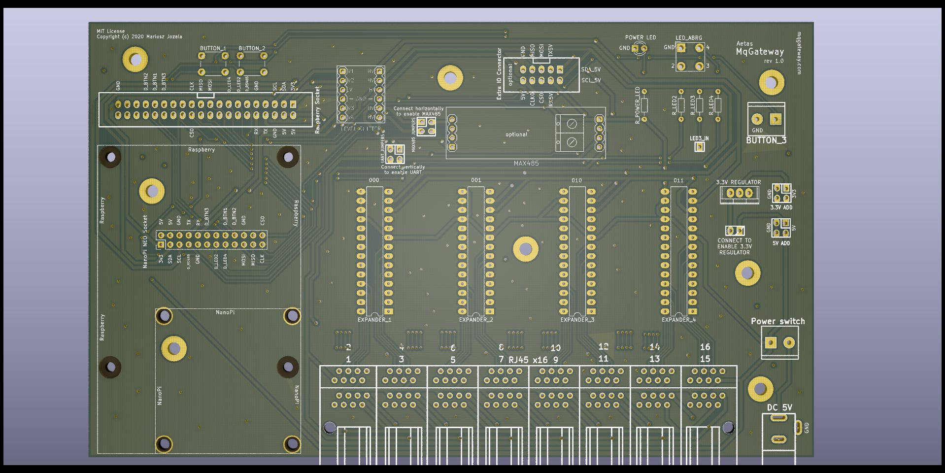
Mainboard layout
Mainboard
Main components
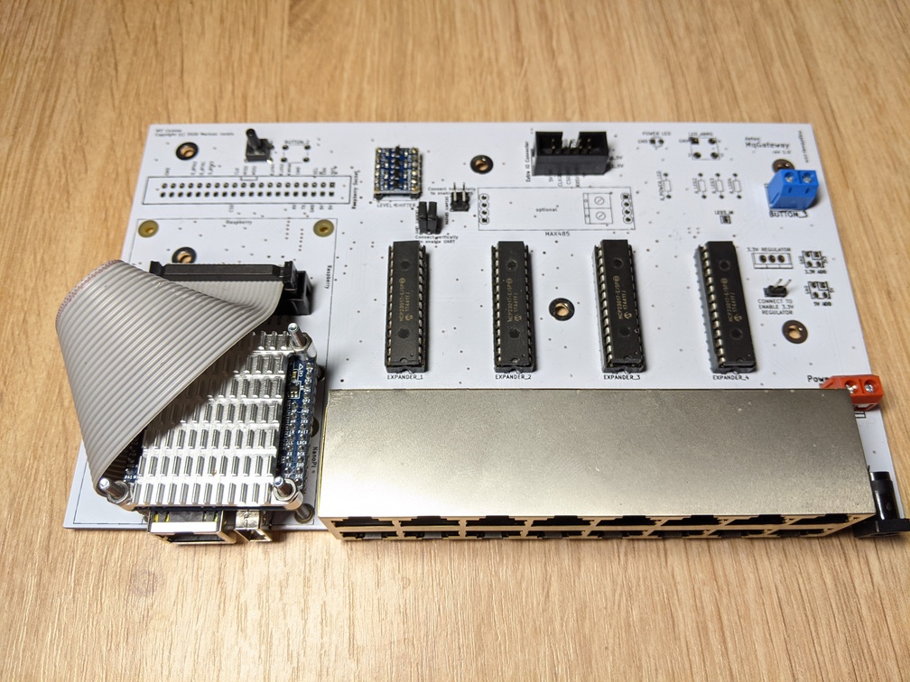
Mainboard is home for the key components of the device.
The most important element is System-On-a-Chip computer (SOC) which controls other components and provides Ethernet connection.
Four 16-channel port expanders MCP23017 has been used to supply 64 digital input/output ports. MCP23017 are connected by I2C protocol
going through 2-way level shifter to shift 3.3V signals from SOC to 5V expanders' signals.
UART port pins from SOC also going through level shifter (3V3<->5V) can got either directly to I/O RJ45 ports or through optional MAX485 module. This can be set on the board with jumpers on the marked pins.
PCB project in KiCAD and Gerber files are available on GitHub and openhardware.io.
I/O RJ45 ports
Sixteen RJ45 ports are responsible for input and output to sensors and devices like relays. Each port provides:
- power (+5V and GND)
- 4 digital input/output wires
- 2 wires used for UART TTL or RS485 communication
See wiring page to learn more about RJ45 ports and role of each wire.
Expander IO Board
An additional board which adds more input/output ports and make possible to use RS485 bus with 12V powered devices.
Currently in development.